
 0 likes
ATOS
1. ATOS PFE vane pump are fixed displacement-twelve-vane pump,
2. 2 and 3 cartridge design with integral hydraulic balancing 4 for high pressure operation and long service life with low noise level.
3. Suitable for hydraulic oils according to DIN 51524 OR synthetic fluids have similar lubricating characteristics.
4. These pumps are available as single, multiple or with through-shaft configuration.
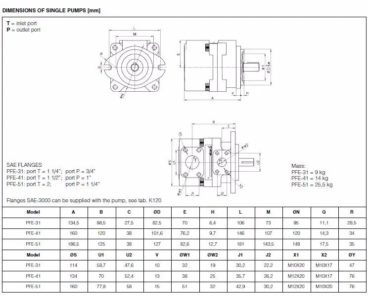
5. Mounting according to SAE J744 standard.
6. Easy installation as inlet and outlet ports can be assembled in any of four relative positions.
7. Easy maintains as the pumping cartridge can be replaced in a few minutes.
8. Wide variety of displacements up to 150 cc/rev. Max. pressure 210 bar .
Hydraulic Vane Pump model as following:
Single PFE series:
PFE-21 series: PFE-21005, PFE-21006, PFE-21008, PFE-21010, PFE-21012, PFE-21016PFE-31 series: PFE-31016, PFE-31022, PFE-31028, PFE-31036, PFE-31044,PFE-41 series: PFE-41029, PFE-41037, PFE-41045, PFE-41056, PFE-41070, PFE-41085PFE-51 series: PFE-51090, PFE-51110, PFE-51129, PFE-51150
Double PFED series:
PFED-32, PFED-42, PFED-43, PFED-53, PFED-54

Model code
PFE X2 - 31 036 /31028 / 1 D T ** /*
1 2 3 4 5 6 7 8 9 10
1. Fixed displacement vane pump
2. Additional suffix for multiple pumps:
X2 = double pump composedof single vane pumps
X3 = triple pump composed of single vane pumps
Eventual suffix for pumps with throughshaft:
XA = for couplingone PFE-31
XB = for couplingone PFE-41 (only for PFE-41 and PFE-51)
XC = for couplingone PFE-51 (only for PFE-51)
XO = with throughshaft, without rear flange
Note:mulitple pumps are assembledin decreasing order of size. See also tab. A190.
3. Size, see section :
31, 41, 51
4. Displacement [cm3/rev], see section
for PFE 31: 016, 022, 028, 036, 044
for PFE 41: 029, 037, 045, 056, 070, 085
for PFE 51: 090, 110, 129, 150
5. Only for multiple pumps PFEX*: type of second (and third) pump
6. Drive shaft, see section and :
cylindrical, keyed for singleand multiple pump (only first position)
1 = standard
2 = long version (only for PFE-41 andPFE-51)
3 = for high torque applications splined
5 = for single and multiple pumps (any position)
6 = for single and multiple pumps (only first position) (only for PFE-31 and PFE-41)
7 = for second and third position in multiple pumps (only for PFE-31 and PFE-41)
7. Direction of rotation (viewed from the shaft end):
D = clockwise(supplied standard if not otherwise specified)
S = counterclockwise
Note: PFE are not reversible
8. Port orientation, see section :
T = standard
U, V, W = on request
9. Design number
10. Synthetic fluids:
WG = water-glycol
PE = phopsphate ester
|
Model |
Displacement cm3/rev |
Max pressure |
Speed range rpm (2) |
7 bar (3) l/min kW |
70 bar (3) l/min kW |
140 bar (3) l/min kW |
210 bar (3) l/min kW |
|
PFE-31016 |
16,5 |
210 bar (1) |
800-2800 |
23 0,5 |
21 3 |
19 5 |
16 8,3 |
|
PFE-31022 |
21,6 |
30 0,6 |
28 4 |
26 7 |
23 10,8 |
||
|
PFE-31028 |
28,1 |
40 0,8 |
38 5,5 |
36 10 |
33 14 |
||
|
PFE-31036 |
35,6 |
51 1 |
49 7 |
46 12,5 |
43 17,8 |
||
|
PFE-31044 |
43,7 |
800-2500 |
63 1,3 |
61 8 |
58 15,5 |
55 22 |
|
|
PFE-41029 |
29,3 |
41 0,8 |
39 5,5 |
37 10 |
34 14,7 |
||
|
PFE-41037 |
36,6 |
52 1 |
50 7 |
48 12,5 |
45 18,3 |
||
|
PFE-41045 |
45,0 |
64 1,3 |
62 8,5 |
60 16 |
57 22,6 |
||
|
PFE-41056 |
55,8 |
80 1,6 |
78 11 |
75 21 |
72 28 |
||
|
PFE-41070 |
69,9 |
101 2 |
98 13,5 |
95 26 |
91 35 |
||
|
PFE-41085 |
85,3 |
800-2000 |
124 2,4 |
121 16 |
118 32 |
114 43 |
|
|
PFE-51090 |
90,0 |
800-2200 |
128 2,7 |
124 17 |
119 33 |
114 45 |
|
|
PFE-51110 |
109,6 |
157 3,2 |
152 21 |
147 40 |
141 55 |
||
|
PFE-51129 |
129,2 |
186 3,7 |
180 25 |
174 47 |
168 65 |
||
|
PFE-51150 |
150,2 |
800-1800 |
215 4,2 |
211 29 |
204 55 |
197 75 |
(1) Max pressure is 160 bar for /PE and/WG versions
(2) Max speed is 1800 rpm for /PE versions; 1500 rpm for /WGversions
(3) Flow rate andpower consumption are proportional to the rotation speed
MAIN CHARACTERISTICS OF VANE PUMPS TYPE PFE-*1
|
Installation position |
Any position. |
|
Loads on the shaft |
Axial and radial loads are not allowed on the shaft. The coupling should be sized to absorb the power peak. |
|
Ambient temperature |
from -20°C to +70°C |
|
Fluid |
Hydraulic oil as per DIN 51524...535; for other fluids see section |
|
Recommended viscosity max at cold start max at full power during operation min at full power |
800 mm2/s 100 mm2/s 24 mm2/s 10 mm2/s |
|
Fluid contamination class |
ISO 19/16 (filters at 25 µm value with β25 ≥ 75 recommended) |
|
Fluid temperature |
-20°C +60°C -20°C +50°C (/WG seals) -20°C +80°C (/PE seals) |
|
Recommended pressure on inlet port |
from -0,15 to 1,5 bar for speed up to 1800 rpm; from 0 to +1,5 bar for speed over 1800 rpm |


 Click enlarge Image